 Zac Garby
 Hackathons
*
Hackathons
* Publications
 CV
CVMesh Geometry Extraction
First Place
13 May 2026, NIO Student Hackathon
This was a bit of a different one, but I really enjoyed it!
I’ve not taken part in a hackathon organised by a company before, as opposed to a student body. Nor have I taken part in a longer-term online “asynchronous” hackathon. Nor one with a prescribed task. Well of course the unlimited supply of energy drinks and pizza that we get used to was dearly missed, but it really was a lot of fun nonetheless.
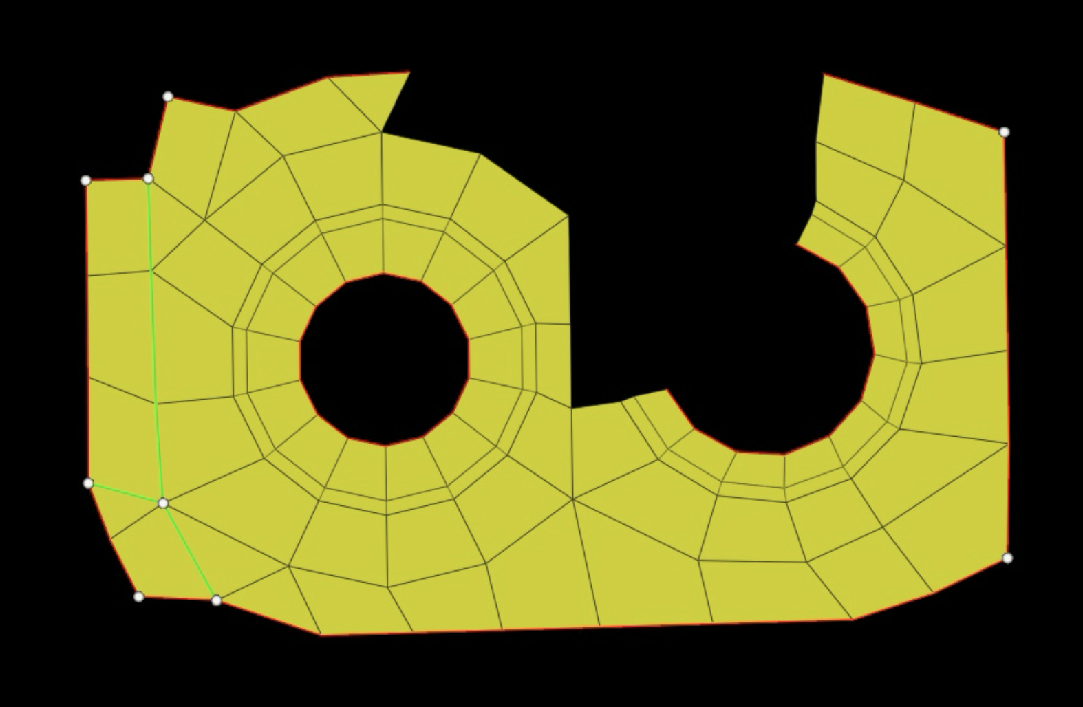
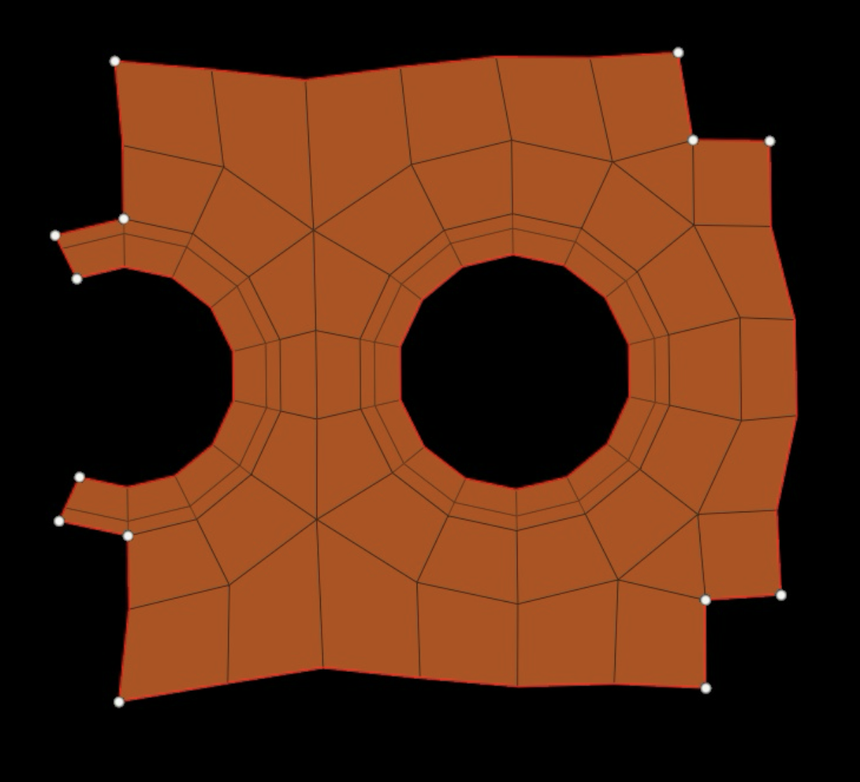
The task revolved around one hundred JPEG images in this format:
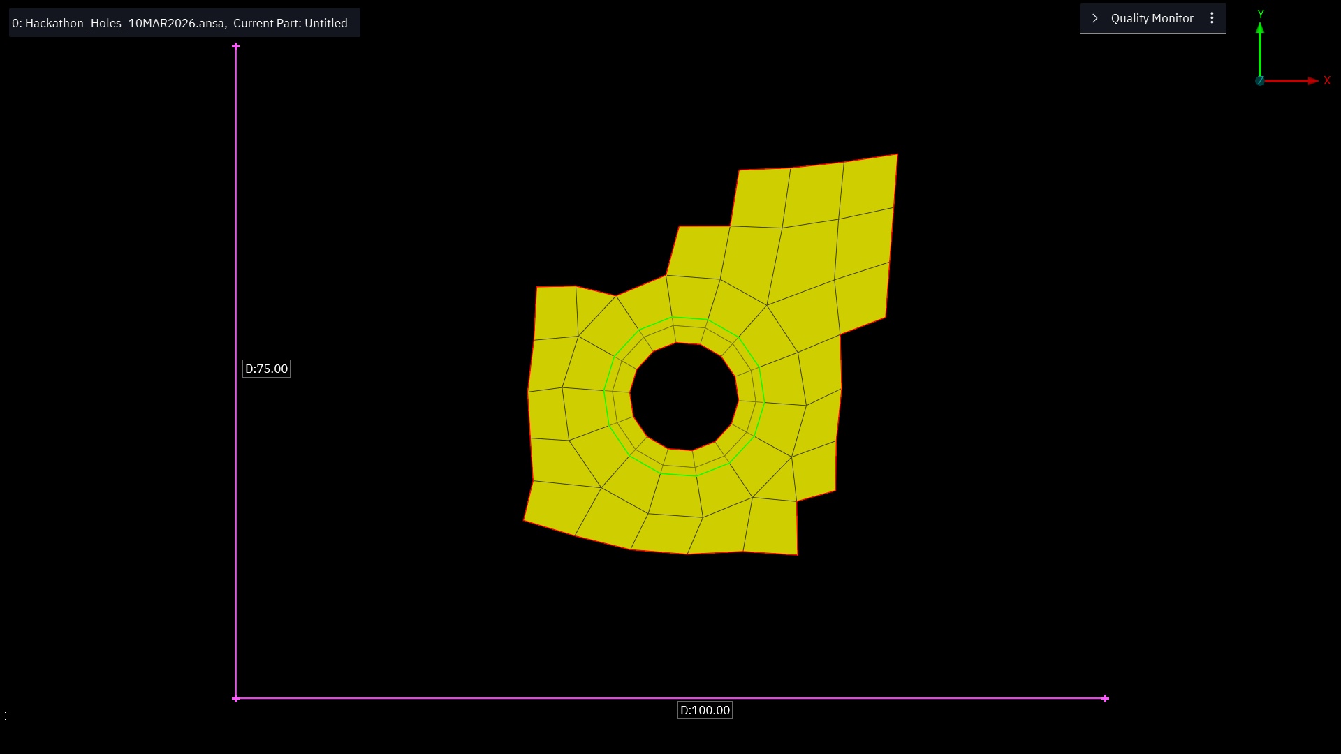
The pink lines denote the axes, and the bright yellow shape is a “thing” of ostensible interest. Our task was to take these images and extract the geometry of each polygon–quadrilateral or triangle–making them up. The coordinates were to be as precise as possible, relative to the axes.
The approach
So my first thought, if I’m honest, was “this will be easy right?”. I remember some things about the image processing module I took as an undergrad, and there were definitely some algorithms back then for extracting line-equations from the straight lines in an image. Then isn’t it just a matter of finding all of these and intersecting them?
There were some difficulties. One: the images are not in great shape. They appear to be screenshots of some CAD software, and in some cases the user seems to have clicked and highlighted some nodes, rendering them a different colour. In other cases, there is a cursor, or some circles attached to some nodes. Also, the colour of the polygons inexplicably vary throughout the images, and sometimes the contrast is so poor that distinguishing things properly is difficult.
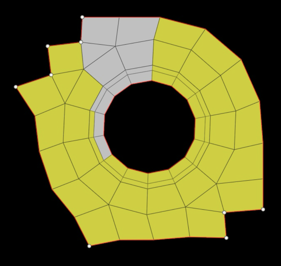
To start with, things will be easier if we can reduce the shape to a binary image and the pixels-wide lines to a single-pixel-wide “skeleton”. A sequence of image processing algorithms does this for us:
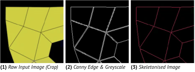
Skeletonisation is the tricky step. Sometimes a vertex will have a “node” on it in the image: a circle overlayed, maybe eight pixels in diameter. Amber did this part, and came up with a very clever solution: segmenting the image and removing any segments that look like these circles. Then, the skeletonisation doesn’t see them. This does mean, however, that the “bones” of the skeleton may not join up precisely at these vertices. On to that later…
Separately, Adrian uses the Ramer–Douglas–Peucker algorithm to segment the image into all of its constituent polygons, identifying them by a “minimum” number of vertices; somewhat a bounding box for each.
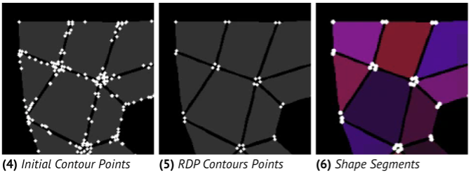
This takes place separate to skeletonisation, and also subject to some filtering, so while the polygons obtained here are roughly correct and do correspond to the real shapes, their corners may be several pixels away from the ground truth.
My task was to bridge these two.
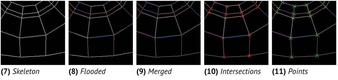
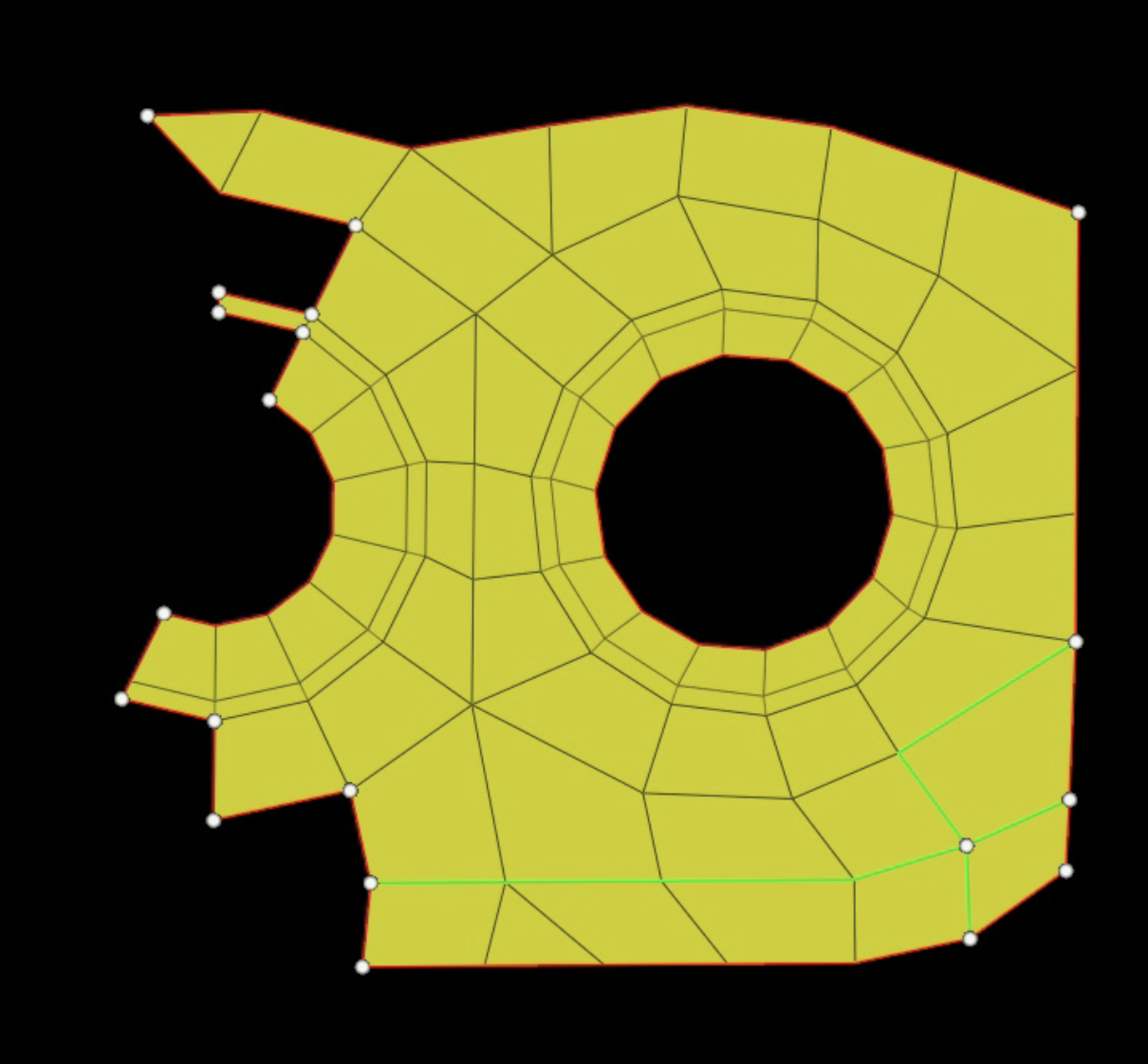
From the skeletonised image, I detect all of the straight lines. The method is a little unconventional, but extremely precise. I flood-fill the pixels of the skeleton, and flood until we reach a “vertex”. That is: a pixel with more than two neighbours. At this point, the line segment must have ended. The flood-fill also keeps track of a “direction” that it moves in, and will finish flooding when the direction of the line changes too sharply from this established heading.
We flood fill untouched pixels until as in (8) above, all of the pixels are labelled. There may be multiple labels for one line segment though, so we merge these based again on a directionality measure (the dot product of their headings). Then we are in a position to compute the intersections of each pair of line segments that lie close enough, extracting, down the sub-pixel, the precise intersection locations.
In the end, we can project the vertices of the polygons obtained via the earlier RDP algorithm into these more precise coordinates, and we are done!
The were of course some difficulties, and a lot of it came down to tweaking the lower-level image processing functions’ parameters. How much do we threshold? Adaptive or not? Any blurring? How do we deal with low-contrast colours?
Results
The last day of the hackathon, we all went round to Adrian’s at 2pm with the intention of finishing off the final bits, submitting, and then playing some board games. In the end, we were up there until midnight tweaking these parameters and working the accuracy of our solution up and up. We set up a little Python UI to evaluate the solution against all one hundred example cases.
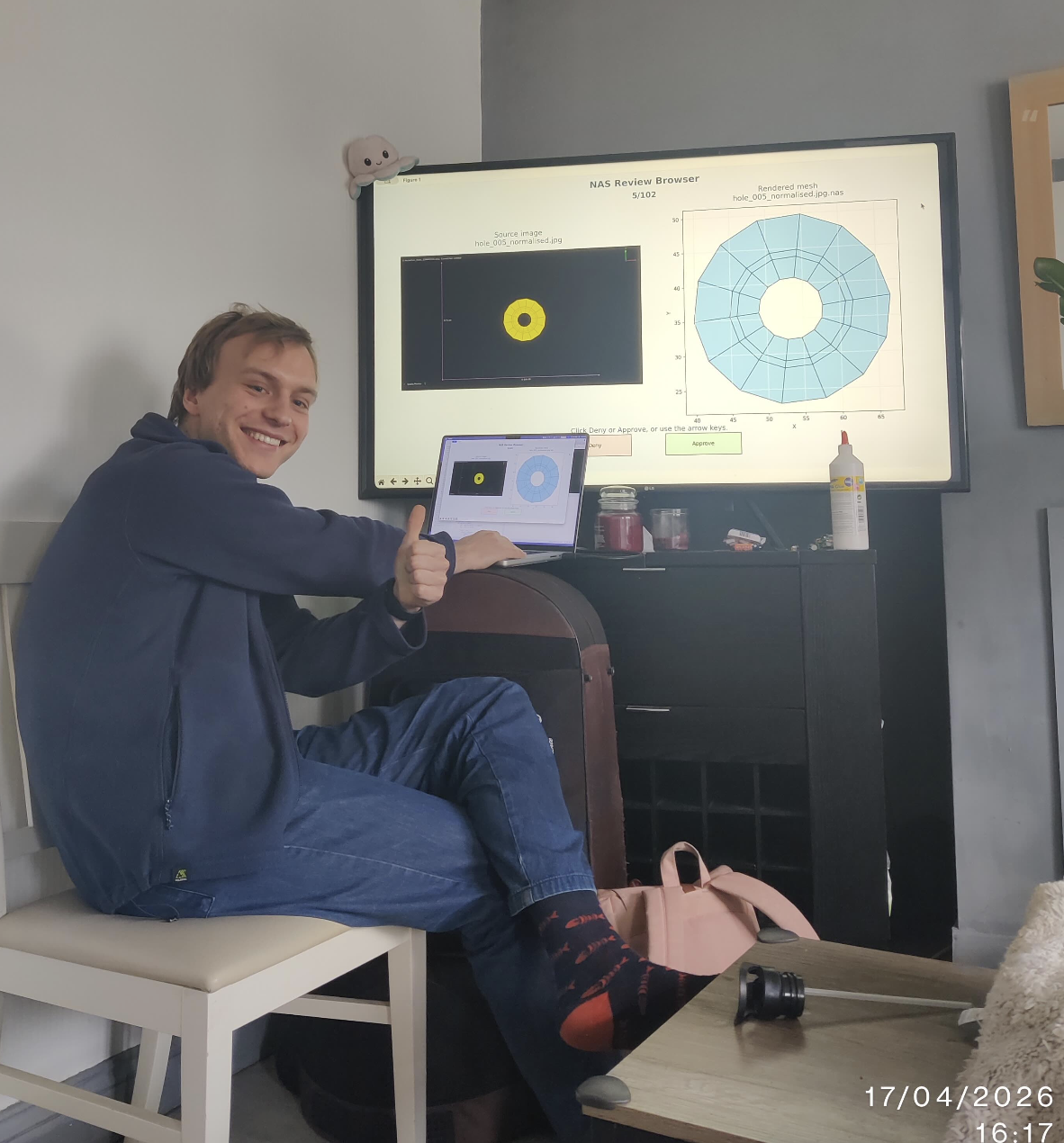
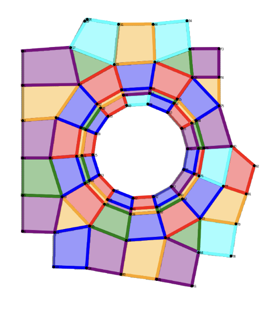
You would not believe the satisfaction when we saw this:

I think we all went a little insane. There were a handful of images that were so difficult, we spent many hours debugging each one. These polygons are now burned into my mind forever, and I’m sure I’m sure that I can now recreate shape 56 from memory.
You can read more about our approach in the report that we submitted alongside.